Scroll ⇧ to 'Contact Us'
Scroll ⇩ to 'Meet Our Team'
Scroll ⇩ to 'Meet Our Team'

EDGECAM Turning provides functionality for a wide range of machine tools, including 2-Axis lathes, multi-turret configurations, sub-spindle turning centers and mill/turn machines. EDGECAM fully supports turning centers including Bar Pull and Feed, Part Pick Off, Balanced and Mirrored Turning, and Turret Synchronization.
☑ Increase machine tool utilization
☑ Reduced programming time
☑ Reduce component cycle time
☑ Eliminate programming errors and reduce potential scrap
☑ Reduce machine tool prove out by graphically simulating the tool path
☑ Avoid collisions and expensive damage to machine tool
☑ Full support for canned cycles
☑ Reduce tooling inventory and stock
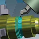
EDGECAM produces advanced rough and finish turning cycles, together with support for facing, boring and drilling in either canned cycle or longhand format. Toolpath calculation takes into consideration the complete tooling insert and tool Holder including the “F” distance and previously machined material to avoid gouging and eliminate air cutting. Ease of use and an understanding that cycle times are critical, especially on multi-configuration mill/turn machines, underpin the development of EDGECAM’s turning functionality. EDGECAM offers support for Sandvik Coromant Wiper inserts for turning tools, allowing these productivity enhancing inserts to be used reliably in all aspects of production machining.
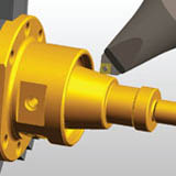
EDGECAM has the ability to keep the stock updated live within the sequence tree. The stock model is rest material, or material that hasn’t been machined. Subsequent toolpaths will automatically detect the rest material resulting in 100% efficiency for any turning toolpath throughout the EDGECAM sequence. Update stock is supported from the most basic 2 axis turning center, right through to a CYB multi turret sub spindle Mill / Turn. When back turning into a recess or groove it’s important that the back turning cycle knows the current condition of stock to avoid air cutting and potential collisions on the approach into the recessed area. On a sub spindle turning center, when a component is transferred from the main spindle to the sub spindle, the live stock transfers with it. Any subsequent machining on the sub spindle will detect the stock in the state that it left the main spindle which ultimately provides the most efficient machining sequence possible.
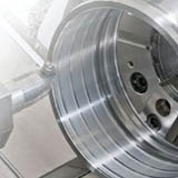
It is imperative that not just the tool in contact with material is checked for collisions, but also tools that are not in use on a turret. Most turning centers offer a relatively small working envelope that can be collision rich. A good example of this is on static turrets where tools such as boring bars, can extend out further than the tool in cut. EDGECAM will not only collision check the tool in cut but also all of the tools on the turret against the machine tool kinematics, fully supporting Mini Turrets, capto tooling and programmable steadies.
When machining inside a bore, loose material can build up around the insert which can result either result in insert failure or severely decreased tool life. EDGECAM will allow you to retract tool out of a bore or away from a diameter after a set numbers of cuts. The user can retract the tool mid cycle, to a known position, after a set number of cuts to clear any loose material out of the bore.
EDGECAM fully supports turning centers with a sub spindle & twin turrets, including :
☑Bar feed
☑ Part pick and return
☑ Running in conjunction with the main spindle
☑Balanced turning
☑ Z lag options improving metal removal
☑ Mirrored turning
☑ Turret synchronization and simulation
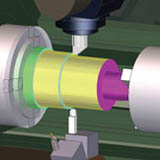
EDGECAMs turning cycles offer the ability to specify offsets to individual turned diameters, bores, grooves and faces. This function is useful where a turned component needs some elements to be finished turned, and others to be left a grinding allowance for subsequent machining or heat treatment.
Most systems on the market today will only allow you to set a constant offset, where as EDGECAM gives the user full control over offsets for each individual element on the turn feature.
Sub contract machinist do not always have the ability to go back to their client to ask them to revize the design to include the chamfers or break edges, even though they have been asked for on the engineering drawing. EDGECAM turning cycles offer the machinist the ability to specify a break edge where a chamfer hasn’t been included on the model supplied to them by their client.
This function within the finish turning cycle alternates the cut direction on the finish turn profile so the tool is always down cutting or it never drags up the face. This give the enhanced tool life and achieves a superior surface finish.
TRADITIONAL grooving cycles wear the tool on one side after the initial full width cut. With Sequential Castellation grooving, the tool starts at one groove edge and moves to the other edge, producing full width cuts.
It then goes back and removes the ‘rings’ left behind by the first cutting pass. This ensures that the load on the grooving tool is on the front of the tool, opposed to the sides. It also ensures even wear on the insert.
To keep the tool push off on a long diameter to a minimum, EDGECAM have developed a section strategy where the user can break the rough turn cycle into sections. The user sets a Z break distance and the roughing cuts are divided into short sections.
This function is to Prevent notches wearing into the tool. Cuts are alternately ‘ramped’ then ‘normal’. During the ramped cuts the cut depth gradually reduces to zero. The next cut (which will be ‘normal’ and starts at the same cut advance) then removes the leftover ramp. If a ramped cut is interrupted by the profile, it follows the profile until it re-joins its ramped path.