Scroll ⇩ to 'Meet Our Team'


VISI Mould provides the complete mold tool design solution based on industry specific automation that guides the user through the mold development process. Dynamic operation previews provide the designer with a 'real time' view of how component changes will affect the tool design.
☑ Automatic recognition of design changes
☑ Draft angle visualization
☑ Multiple split line calculations
☑ Core & cavity model separation
☑ Dynamic 3D tool design
☑ Customisable supplier catalogues
☑ Intelligent component editing
☑ Slides, lifters and flexible up & away units
☑ 3D cooling with collision check
☑ Associative tool detailing
☑ Automatic B.O.M. creation
☑ Seamless link to manufacturing
VISI can work directly with Parasolid, IGES, CATIA, Creo, UG-NX, STEP, Solid Works, Solid Edge, Inventor, ACIS, DXF, DWG, JT Open, STL and VDA files. The extensive range of translators ensures that users can work with data from almost any supplier. The ability to skip corrupt records during the import process provides a platform from where the most inconsistent data can be managed. Very large files can be handled with ease and companies working with complex designs will benefit from the ease with which their customer’s CAD data can be manipulated.
VISI provides a dynamic structure from where it is possible to work with either solid, surface, wireframe or a combination of all three without any restrictions. Solid modelling has become a fundamental cornerstone of design but is often limited to prismatic or basic geometry. Solid modelling commands include boolean technology such as unite, subtract, extrude, revolve, sweep, cavity, intersect and hollow. Surfacing technology however provides a different set to tools and techniques for more organic, free-form geometry creation. Surface modelling functions include ruled, lofted, drive, sweep, n-sided patch, drape, tangent, draft, revolved and piped surfaces. These modelling commands combined with advanced surface editing make it easy to heal imported geometry or construct the most complex 3D data
Essential model preparation tools are available to automatically inspect model data for molding feasibility, redundant geometry, sliver faces and geometry inconsistency. The draft analysis provides the ability to quickly interrogate a model using user-defined color draft zones to easily identify undercut and non drafted faces. Duplicate geometry can be highlighted, extracted and automatically isolated into warning layers. Sliver face detection and automatic removal provides the ability to delete potentially problematic faces whilst maintaining solid topology. Finding potential design issues at this early stage will generate huge time savings further along the design process.
A number of methods are available to automatically generate the optimum split line around a component. Interaction with the computer generated result through a highly graphical interface allows the user to adjust the split line to suit individual design requirements. Once complete, it is possible to extract the split line result as either curve geometry or to automatically split the model into the relevant core, cavity or side moving zones. A comprehensive suite of surfacing tools and a split plane manager combine to create a powerful tool for the generation and management of the most complex parting and shut off faces.
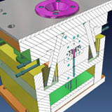
The tool assembly allows the designer to quickly construct a mold base layout and related components. Using a parametric structure based on libraries from leading suppliers including Hasco, DME, DMS, Strack, Meusburger, Cabe, Ceni, Danly, FCL, Futaba, LKM, Pedrotti, Rabourdin, Siam, Sideco, Siderurgica, Siscat, TVMP, UMC, VAP and Victoria, access to the parameters of each individual plate ensures that modification of the tool layout is quick and efficient. Any change to the plate dimensions will automatically adapt any connecting standard component. Part list information is automatically created and can be exported as an external spreadsheet for downstream processes such as detailing and stock ordering.
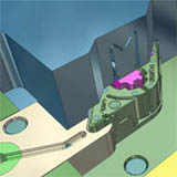
>Dedicated tools for the creation of undercut release mechanisms such as side actions, lifters and flexible up & away units are all available. The proprietary parametric component library enables the designer to dynamically construct around the molding undercut feature and instantly view the impact on the tool design.
The repetitive tasks of the designer are greatly reduced by the use of intelligent standard components from over 35 different suppliers. The length of screws and other components will automatically adjust to suit differing plate thicknesses and rule based parameters. Ejector pins are automatically trimmed to length to match the required 3D cavity form. To prevent rotation, pins can also be locked from turning with a choice of multiple locking methods.
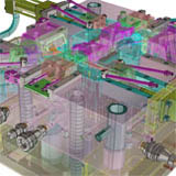
Cooling channels can be easily inserted using the dedicated cooling wizards. Simply sketch the path of the cooling channel and the wizard gives the designer full control over position and sizes, providing automatic proximity checks to ensure cooling lines do not interfere with other tooling elements. Standard cooling line fittings can be easily inserted from leading supplier libraries. Any cooling circuit can be exported as a design template and re-used on a different tool design. If the bolster sizes are different, the cooling circuit can be automatically adapted to coincide with the new plate sizes.
A complete set of 2D detailed drawings can be generated directly from the solid tool assembly. This includes fully editable 2D and isometric sections views, automatic plate dimensioning and hole type and position tables. Individual details can be created from any component in the assembly and displayed as a mixture of 3D rendered and 2D drawings. Any standard catalogue component will have the correct detail representation within a section view. A change in the solid model will result in a modification to the 2D view along with any fully associative dimensions. Parts list table items and their respective balloon references can be added to the drawing using dedicated assembly management tools.
Due to the integrated nature of VISI, manufacturing of individual plates can be completed using feature recognition. Drilled hole features and apertures are automatically selected with the correct drilling cycles and 2D milling routines applied. For more complex core & cavity work, VISI Machining can be used to generate 3D - 5 axis conventional and HSM cutting toolpaths. Keeping the model within the same product environment throughout the entire project, from design to manufacture will guarantee data consistency and greatly smooth the design process.


